


Master AutoCAD 2D Mechanical Drawing
How mechanical parts are actually drafted in 2D — projection, sections, tolerancing and the drawing conventions a shop floor expects.
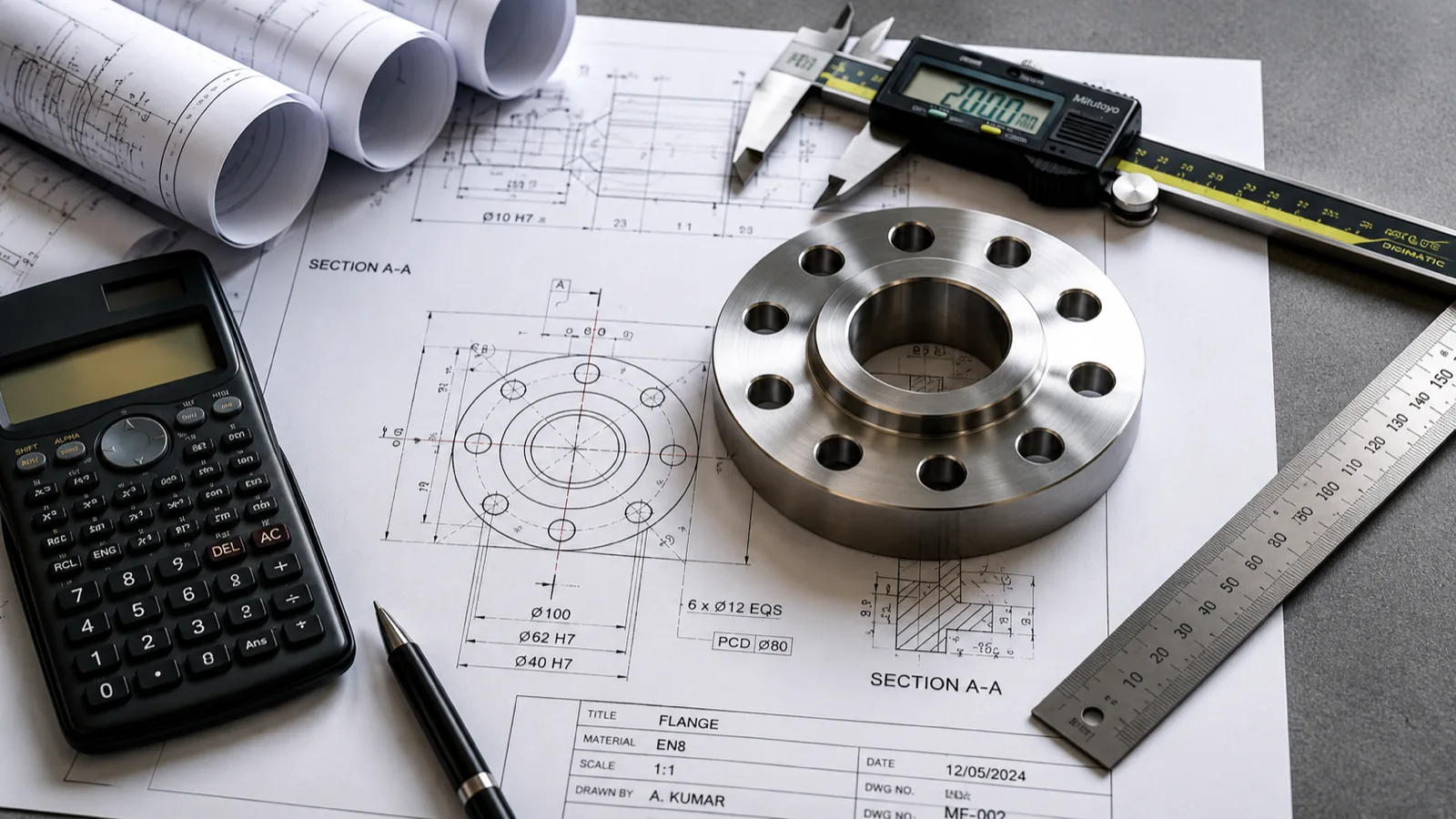
Orthographic projection is the foundation
Mechanical drawing is a language, and projection is its grammar. First-angle and third-angle projection describe the same part differently, and getting the convention wrong makes a drawing actively dangerous rather than merely unclear.
Sections and auxiliary views
Internal features cannot be described with hidden lines alone once a part gets complex. Full sections, half sections, offset and revolved sections each exist for a reason, and picking the right one is a design decision.
Dimensioning with intent
Every dimension on a drawing is an instruction to somebody making the part. Dimension from datums that reflect how the part functions and how it will be held during machining, not from whichever edge is convenient.
Tolerances and fits
A dimension without a tolerance is an unanswered question. Understanding clearance, transition and interference fits — and where each is appropriate — is what makes a drawing manufacturable rather than aspirational.
Title blocks, BOM and standards
Revision control, part numbers, material specification and surface finish are not administrative overhead. They are how a drawing survives contact with a real supply chain.
Where this leaves you
2D mechanical drafting is often described as obsolete. It is not — in most Indian manufacturing and fabrication firms, the issued drawing is still 2D, even when the design was modelled in 3D. It remains directly employable.